ECE Projects
|
ECE Projects |
Electronic Projects AudioRF
Circuits |
AC Lamp Flasher Circuit
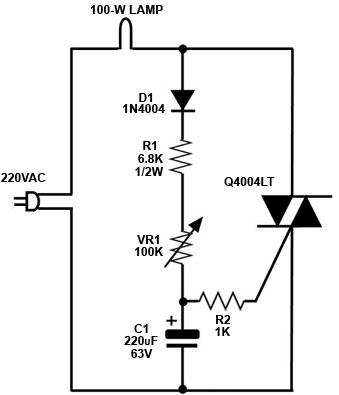
Figure 1. AC Lamp Flasher Circuit The circuit in Figure 1 is an AC lamp flasher circuit, i.e., a circuit that makes an AC lamp or bulb flash continuously at a certain frequency. The flashing frequency is adjustable through variable resistor VR1. The AC lamp is driven by the Q4004, which is a quadrac. The lamp therefore turns 'on' only when the Q4004 is conducting. The Q4004 conducts only when the voltage at its gate exceeds its 'threshold' level. The trigger voltage at the gate of the Q4004 is taken from the voltage across capacitor C1. C1 charges up from the AC line through the diode 1N4004, resistor R1, and variable resistor VR1. The 1N4004 rectifies the AC voltage to allow C1 to charge up. The voltage across C1 eventually exceeds the 'threshold' level, and triggers the Q4004 to conduct, turning on the AC lamp. C1 discharges through the gate of the Q4004 once the latter conducts, decreasing the voltage across C1 to a level below the threshold voltage, causing the Q4004 and the AC lamp to turn 'off'. The entire cycle repeats again, in effect causing the AC lamp to turn 'on' and 'off' repeatedly. |
|