ECE Projects
|
ECE Projects |
Electronic Projects AudioRF
Circuits |
Basic Monostable Multivibrator Circuit
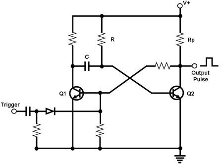
Figure 1. Circuit Diagram for a Basic Monostable Multivibrator The circuit in Figure 1 is that of a monostable multivibrator. This circuit outputs a single pulse whenever it receives a 'trigger'. The pulse width of the output pulse is determined by a resistor-capacitor combination in the circuit, as explained below. In its untriggered state, Q2 is normally conducting and is pulling the output to ground. Meanwhile, Q1 is 'off' because its base voltage is 'low' while capacitor C is not charged. When a pulse is applied to the trigger input, Q1 is momentarily turned on, pulling the base voltage of Q2 to 'low', thereby turning off Q2. This causes the output to go high because of the pull-up resistor Rp. With Q1 conducting, capacitor C charges up through R, continuously increasing Q2's base voltage. Eventually it becomes high enough to turn Q2 'on'. Once Q2 conducts, the output is pulled down 'low' again, in effect ending the output pulse. This also, pulls down Q1's base voltage, turning Q1 'off'. C bleeds off its excess charge into Q2's base until equilibrium is restored. The circuit is then ready once more to be triggered to generate an output pulse. |
|