ECE Projects
|
ECE Projects |
Electronic Projects AudioRF
Circuits |
DC Voltage Polarity Inverter Circuit
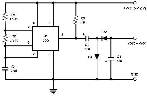
Figure 1. Circuit Diagram for a DC Voltage Polarity Inverter (capacitor values are in microF) This is a circuit that outputs a -Vcc voltage, i.e., an output voltage Vout that is almost the same level as Vcc but opposite in polarity. Note that this circuit can only provide a limited amount of negative current at Vout, i.e., just enough to power small dual-supply IC's. The circuit uses a 555 timer IC configured as an astable multivibrator, i.e., it generates a continuous square wave signal of a set frequency as long as its reset pin (pin 4) is held high. This means that the 555 output toggles between '1' and '0' continuously at the set frequency. When the 555 output (pin 3) is at logic '1', its voltage level is very close to the Vcc level, causing C2 to charge to this level through D1 while D2 isolates C3 from the 555 output. When the output is at logic '0', C2 can not discharge to pin 3 through D1 because D1 is not conducting. C2, however, can discharge its near-Vcc voltage to pin 3 through D2. This, in effect, puts the anode voltage of D2 (Vout) at close to negative Vcc. C3 stabilizes this -Vcc voltage with respect to GND. |
|