ECE Projects
|
ECE Projects |
Electronic Projects AudioRF
Circuits |
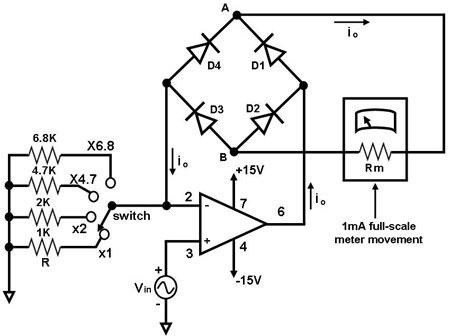
Low-Voltage AC Voltmeter
Figure 1. Circuit Diagram for an AC Voltmeter The circuit shown in Figure 1 is a simple AC voltmeter for measuring low AC voltages. The main component of this circuit is an operational amplifier (such as the 741 or 351), configured as an amplifier whose feedback circuit is a diode bridge full-wave rectifier. An ammeter is attached to the rectifier circuit as shown in Figure 1 so that the op amp's output current in both the positive and negative cycles flows through it in only one direction. In effect, the average of the op amp's output ac current io, which passes through the ammeter as a dc current, is measured by the ammeter. With full wave rectification, the meter current is given by: io = 0.9 Vin/R, or Vin = 1.1 ioR. Note that this project requires calibration so that the meter will register the rms value of the input voltage Vin. |
|