ECE Projects
|
ECE Projects |
Electronic Projects AudioRF
Circuits |
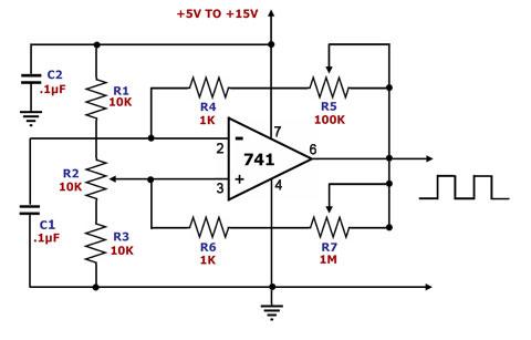
Op Amp Square Wave Generator
Figure 1. Square Wave Generator Circuit Diagram This is a square wave generator circuit. The main component of this circuit is the 741, a general-purpose operational amplifier. This circuit employs a single power supply Vs that can range from +5V to +15V. The square wave output of this circuit is easy to adjust. 'Timing' is defined by C1, R4, R5, R6, and R7 while duration is defined by R1, R2, and R3. Pulse symmetry is achieved by making the resistance from pin 3 to ground equal to the resistance from pin 3 to Vs. If this is desired, then R1, R2, and R3 may simply be replaced by two equal resistors from pin 3, one of which is tied to Vs while the other is tied to ground. |
|