ECE Projects
|
ECE Projects |
Electronic Projects AudioRF
Circuits |
Peak Dectector Circuit
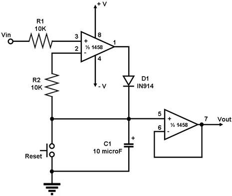
Figure 1. Circuit Diagram for a Peak Detector This is a circuit that detects the peak voltage of the input waveform Vin and outputs it as Vout. The circuit uses a dual operational amplifier IC, the 1458, which is a single IC package that houses two individual op-amps. In this circuit, the first op-amp is used as a voltage follower whose output is used to charge the capacitor C1 through D1. As such, the voltage to which capacitor C1 charges up to is the maximum voltage that the input waveform reached, i.e., its peak voltage. The second op-amp of the 1458 is used as a buffer that outputs the capacitor voltage with negligible loss in the capacitor charge. The reset switch is used to discharge the capacitor if a new input peak voltage needs to be detected. |
|