ECE Projects
|
ECE Projects |
Electronic Projects AudioRF
Circuits |
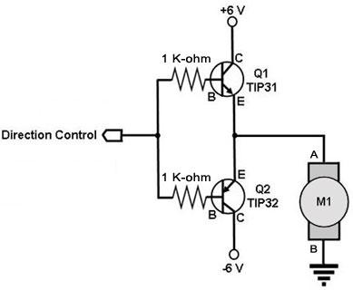
Two-Transistor DC Motor Driver
Figure 1. Circuit Diagram for a DC Motor Driver Using Transistors This is a circuit for controlling an ordinary DC motor using a pair of transistors (1 NPN and 1 PNP). Note the dual supply of this circuit (+6V and -6V). A DC motor runs in one direction if the required voltage is applied across its winding and runs in the opposite direction if the polarity of the applied voltage is reversed. This function can easily be achieved by the circuit above. In this circuit, a positive voltage at the control input turns on Q1 (an NPN transistor) but turns off Q2 (a PNP transistor). This causes current from the +6V supply to flow through the motor from node A to B (ground), making it turn in the forward direction. On the other hand, a negative voltage turns off Q1 and turns on Q2, causing current to flow from node B to node A of the motor, then to the negative supply through Q2, making it turn in the opposite direction. An input of 0 V stops the motor. Note that the values of the base resistors of the transistors (or even the transistors themselves) required by the circuit may be different from those shown in Figure 1, depending on the motor being driven. Experimentation may therefore be required on the part of the hobbyist to make this circuit work. |
|